Filtering Using the Discrete Fourier Transform
In this exercise, we will implement simple filters using the results of the Discrete Fourier Transform (DFT).
An input image is often corrupted by noise, which is typically represented by high-frequency components in the frequency domain. One of the goals of this exercise is to create a filter that removes noise from the input image. Another task is to remove regular vertical bars from an image.
Noise Removal
As mentioned above, noise is typically represented by high frequencies in the frequency domain. In the previous exercises, we implemented both the transformation of an image into the frequency domain using the DFT and the inverse transformation back into the spatial domain using the IDFT. We will now introduce filtering into this processing pipeline.
In the frequency domain, we can apply several types of filters, including low-pass, high-pass, and band-pass filters. To remove noise, use a low-pass filter.
Recall that after the DFT, the low frequencies are located in the corners of the complex matrix, while the high frequencies are located near the centre. To make the filter easier to construct and apply, swap the first quadrant with the third and the second quadrant with the fourth, as shown schematically in Fig. 1.
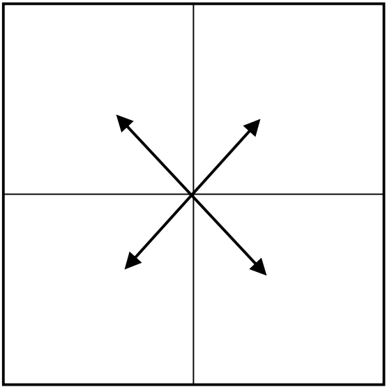
Fig. 1: Quadrant swap.
Next, create a circular mask that is white inside the circle and black outside it, as shown in Fig. 2.

Fig. 2: Circular frequency-domain mask.
The diameter of the circle determines the strength of the filtering. Experiment with different diameters and observe how they affect the result.
To remove high frequencies using a low-pass filter, iterate over the pixels of the mask and set the corresponding values of the complex frequency-domain matrix to wherever the mask is black. For a high-pass filter, do the opposite and remove the frequencies inside the white circle.
After modifying the frequency-domain values, swap the quadrants back to their original positions and use the IDFT to transform the result back into the spatial domain.
An example of low-pass and high-pass filtering is shown in Fig. 3.
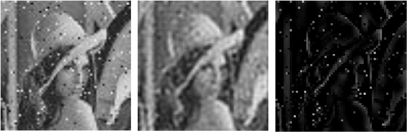
Fig. 3: Input image (left); low-pass filtered image (middle); high-pass filtered image (right).
Removing Regular Vertical Lines
The second task is slightly more complex. Your goal is to determine which frequencies correspond to the regular vertical lines in the input image.
The frequency-spectrum images provided on the exercise website can help you identify the relevant frequency components. By setting the appropriate parts of the complex frequency-domain matrix to , you can suppress the periodic pattern and obtain a result similar to the one shown in Fig. 4.
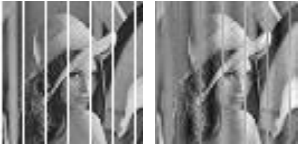
Fig. 4: Input image (left); image after removal of the vertical bars (right).